Egs002 inverter circuit diagram pdf / egs002 manual en power supply Inverter schematics circuits circuit ac simple schematic electrical basic forums using 60hz amplifier buffer ic only power shows gr next Inverter circuits dc ac circuit converter parts list
High Frequency Inverter Circuit Diagram - Soldering Mind
Interlocking gate drivers for improving the robustness of three-phase
Inverter 1000w 24v sine egs002 frequency 220vac schematics transformer
Homemade 2000w power inverter with circuit diagramsInverter as high voltage low current source circuit diagram Inverter circuit diagramMicrotek digital inverter circuit diagram.
Inverter circuit diagram: a complete tutorialInverter circuit diagram seekic Tronix technology: electrical engineering projectsTesting troubleshooting an inverter circuit discussion ~ diagram circuit.
Inverter frequency schematics 100w
Why customer needs low frequency inverter to replace his high frequencyCircuit receiver frequency low diagram build diagrams Operation of 200w inverter circuit diagram1000w inverter circuit diagram / china kayal 1000w dcac pure sine wave.
Super circuit diagram: simple low-power inverter circuit diagramInverter circuit sine diagram modified wave Secret diagram: more circuit diagram for inverterInverter circuit power diagram low simple 1000w 25w schematic small schematics dc 12v ac mosfet 220vac watt 220v circuits amplifier.

Inverter circuit diagram digital microtek pcb layout following complete link click power
Inverter vevor 3000w sine lcd power 24v 120v3000 watt inverter circuit diagram High voltage inverter circuit diagramInverter circuit diagram using sg3524 and mosfet.
Inverter schematicsPhase three gate inverter ti inverters isolated drivers industrial vfd robustness interlocking improving schematic 3phase figure technical 13+ high frequency inverter circuit diagram5kva ferrite core inverter circuit.

Circuit voltage inverter high diagram frequency build circuits source output electronic power transformer step using gr next
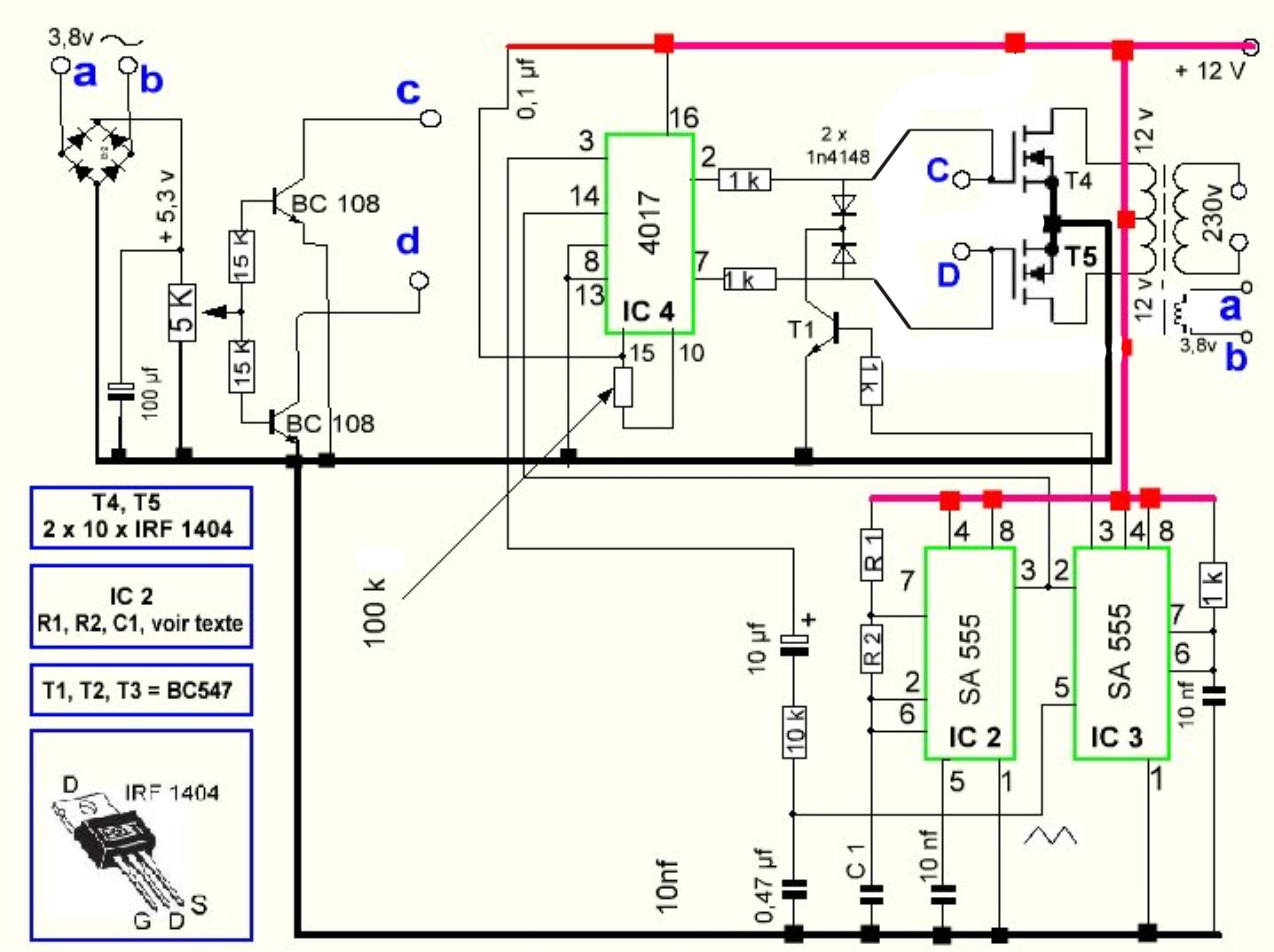
Inverter 3v skema rangkaian transistor mosquito elektronika input lcd dasar voltsInverter diagram circuit egs002 pwm sine wave schematic mosfet theorycircuit frequency circuits sg3524 High frequency inverter circuit diagramCircuit-zone.com.
Inverter mosfet 555 ne555 timer eleccircuit sine sg3524 volts schematics 50hz transformer frequency amplifier figure1Inverter transformerless ic circuits Inverter diagram circuit 3000 watt wiring power charger electronic 12v pure sine aims 3000w pcb schematics board solar dc highInverter circuit diagram pwm 5kva core ferrite sinewave circuits homemade sine board solar transformer working calculation details choose system wave.
What is a high-frequency power inverter?
Inverter circuit sine inverters modified tutorialLow power inverter circuit diagram Diagram block inverter watt 200watt inverters circuit mosfet operation 50hz output circuits oscillator electronic control 200w eleccircuit projects high figureRobots and circuits: inverter circuits.
Inverter voltage high current low circuit diagram source timer schematics ic using labelsInverter circuit power diagram feedback low sponsored links The inverter circuit diagram 2Frequency inverter low customer high feedback another inside.

25w low power inverter
Build a low frequency receiver circuit diagram3 best transformerless inverter circuits Inverter frequency principleInverter circuit 100w diagram schematic watt cd circuits projects using electronics build transistor wave power ac electrical basic project parts.
Vevor 3000w low frequency pure sine wave power inverter dc 24v to acInverter circuit 2000w schematic sine wave dc diagram power pdf pure ac sg3525 homemade sinewave wiring protection overvoltage using driver .